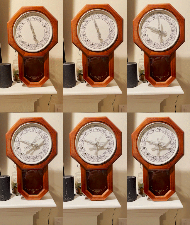
From a combination of reading Harry Potter with my 8 year old and her “simple machines” STEM lessons in school, we decided to embark on building our very own physical location clock. Already having Home Assistant set up and configured for my wife and I, we chose to build upon that along with ESPHome.
You can follow along here to build your own.
Inspiration
For this project, I drew inspiration from the following similar projects
- Magic Clock: Most of the 3D print files for the assembly were used and/or remixed from here.
- Printable Props: Pascal Böcker graciously shared the STLs for the clock hands with me.
Setup
Parts
| Part | Quantity | Price | My Source |
|---|---|---|---|
| nodemcu-32s dev board (38 pin) | 1 | $7-$12 | Amazon |
| ULN2003 Board w/ Stepper Motor | 4 | $10-$14 | Amazon |
| Female to Female Jumper Wires | ~26 | $5-7 | Amazon |
| 6V 2A AC/DC Adapter w/ Breakout | 1 | $10-20 | Amazon |
| Aluminum Telescopic Tubes (1/8, 5/32, 3/16, 7/32) | 1 each size | $7-9 | Amazon |
| Transparent Paper Sheet | 1 | < $1 | On Hand |
| Transparent Vinyl Sticker Sheet | 1 | < $1 | On Hand |
| #10-24 x 3” Machine Screws | 4 | $2-$4 | Big Box Store |
| #10-24 T-Nuts | 4 | $1-$2 | Big Box Store |
| #10-24 Nuts | 24 | $2-$4 | Big Box Store |
| Small Wood Screws | 6 | $1-$2 | Big Box Store |
| 1/2” MDF/Wood Block/Plywood/Scrap Wood | 1 | ? | On Hand |
| White Spray Paint | 1 | ? | On Hand |
| Metallic Silver Spray Paint | 1 | ? | On Hand |
| Super Glue & Wood Glue | 1 | ? | On Hand |
| Old Clock Body (Mine was a Regulator 1114c) | 1 | $25-$35 | |
| Total | < $100 |
3D Printed Parts
| Part | Quantity |
|---|---|
| ULN2003 dual case (base, cover) | 2 |
| Mounting Bracket Base | 1 |
| Mounting Bracket Top (clean or threaded & plug) | 1 |
| Spur Gear 5mm | 4 |
| Spur Gear (1/8, 5/32, 3/16, 7/32) | 1 each |
| Clock Hand (1, 2, 3, 4) | 1 each |
Tools & Supplies
- Phillips Screwdriver
- Exacto Knife
- Super Glue
- Wood Glue
- Wood Clamps
- Spray Paint (White & Metallic Silver)
- Hand saw w/ metal cutting blade
- Wood saw
- Drill & bits
- Pick (helps remove staples)
- Soldering Iron
- (optional) Bench Grinder
Software
The SVGs in the graphics folder were created in Inkscape and are editable to change your locations and names. The names.svg file has a hidden layer with a to-scale copy of the clock hands I printed for alignment. They use the Lumos font face.
Flash Your ESP32
The ESPHome configuration can be found here. With ESP Web Tools, you can flash and configure your ESP32 directly from a supported browser with the compiled firmware by plugging it in and clicking the button below.
The Build
Assembly of the control mechanism was the most difficult part of this project, and I did not take near enough pictures or notes of the process. That being said, a lot of it is pretty self explanitory, so I will give a general overview of the steps I took and some gotchas along the way.
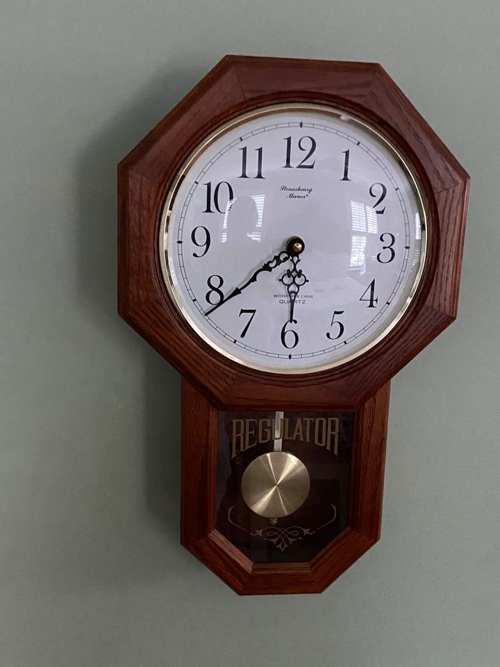
Clock Tear Down
- 4 screws held the glass assembly of the clock face on from the inside of the body.
- The clock hands pull right off - they require some pressure.
- Remove the nut from the clock face, and the old time mechanism should come right out.
- The glass was held in with a plastic support held by two small screws. Remove the glass so it doesn’t break. I also used a razor blade to scrape off the “REGULATOR” text from the glass.
- The face was held on with 4 L brackets on the side of the clock. I removed it for easier access to build the mechanism.
- The clock face was attached with some double sided tape and pulled right off.
- There was a pre-existing 1/2 block of wood in the clock body that was too small and needed to be removed. It was held on with 2 staples, but no glue. I used a pick to pull the staples out.
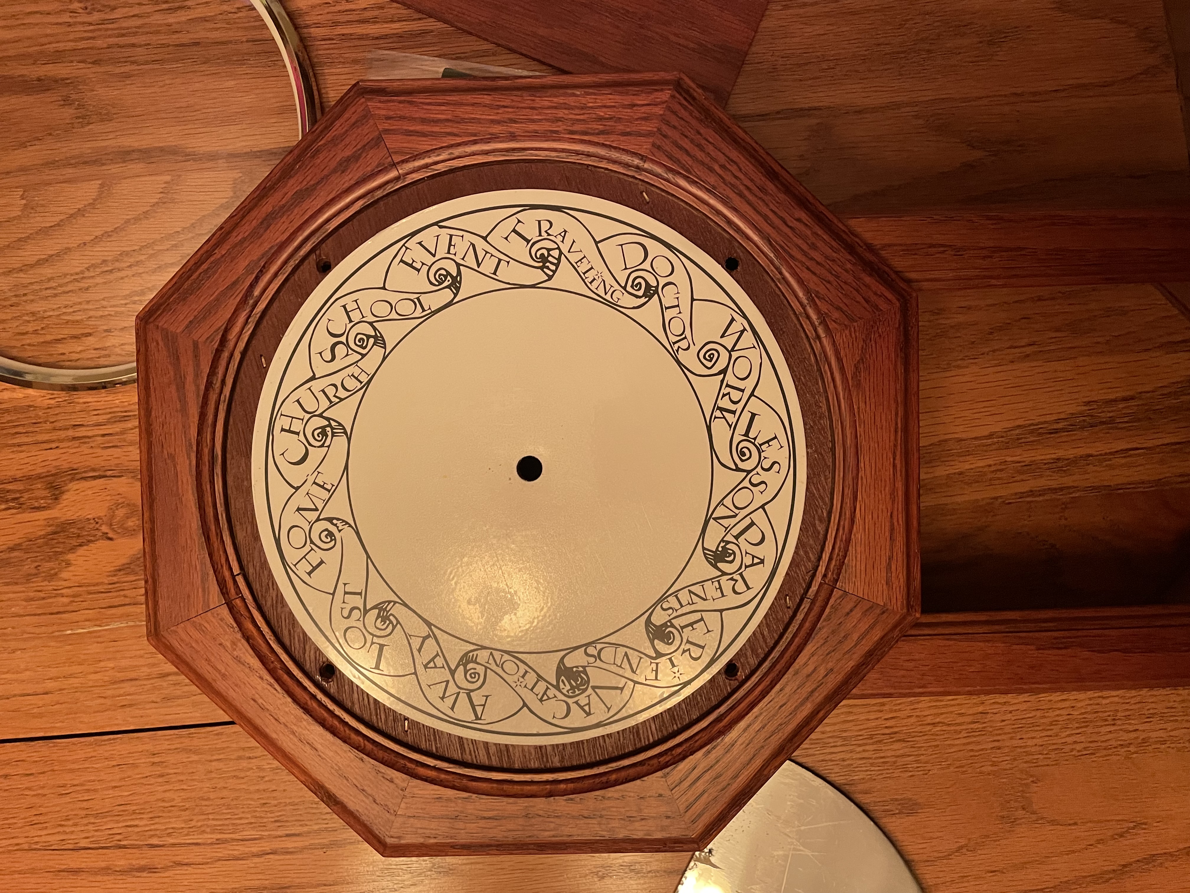
Clock Face
- I spray painted over the aluminum clock face with flat white paint to cover the old numbers.
- I created a new face in Inkscape and printed it on the vinyl sticker paper.
- After the paint dried, I was able to apply the new face to the old aluminum one and trim it down with an exacto knife.
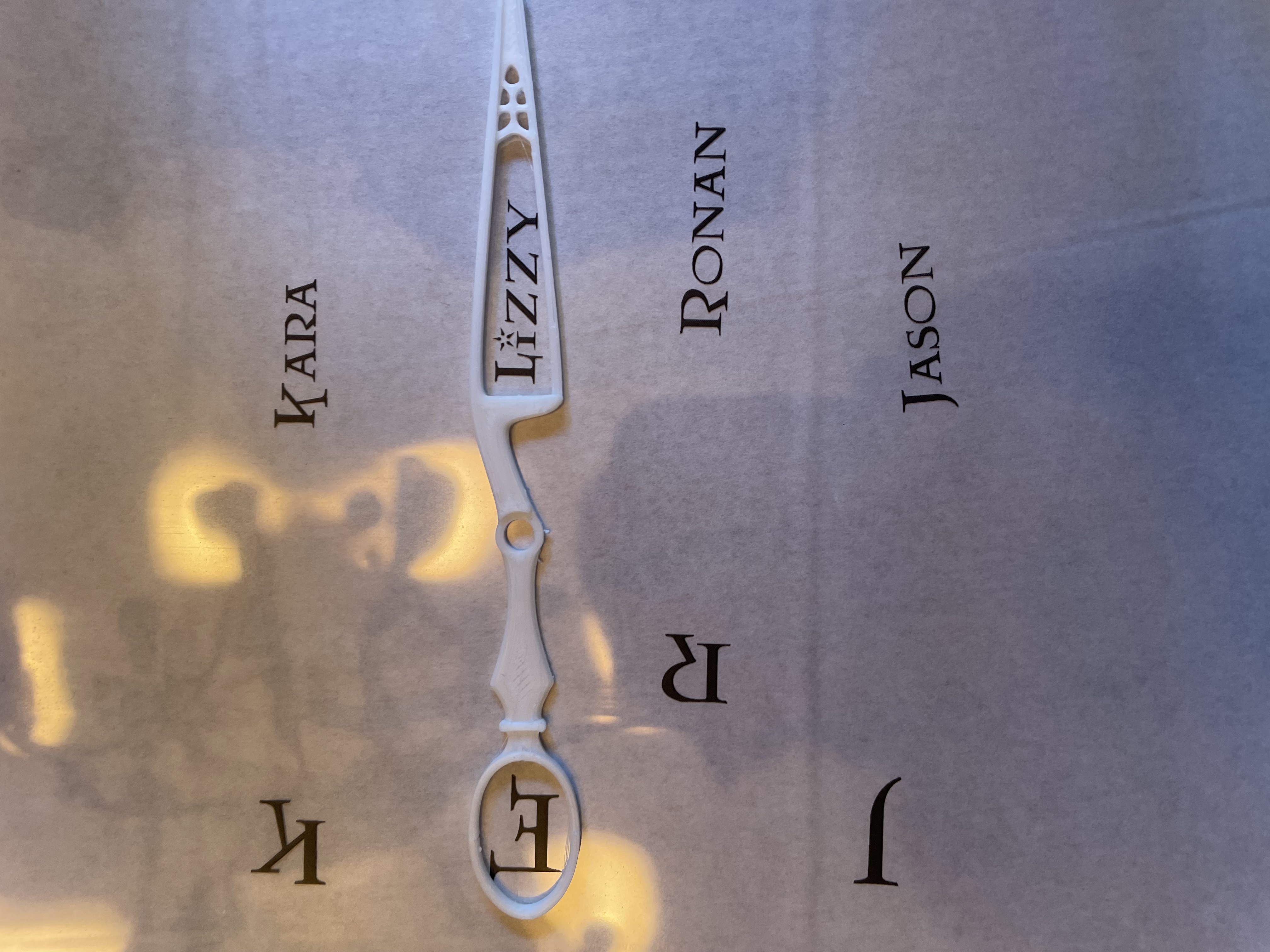
Clock Hands
The clock hands are reproductions of Arthur, Molly, Ron, and Bill’s hands from the film made by Pascal Böcker of Printable Props. I scaled down his originals to fit in my clock face and resized the holes for the aluminum rods I am using.
- Spray paint them Metallic Silver.
- Super Glue them to the transparent paper.
- Cut out the hands with an exacto knife.
Motor Mechanism
Here is where I didn’t take nearly enough pictures, and for that I’m sorry!
- Cut your 1/2” MDF/Scrap Wood/Plywood down to size to fit inside the clock.
- Using the top mounting bracket as a template, drill holes through the wood for the center piece and the 4 #10 screws in the corners.
- Hammer in the T-Nuts to the back of the board.
- Cut off the heads of the 3” #10 screws and thread a nut through to fix the threads. You can use a bench grinder to clean up the cuts, but it’s not necessary.
- Thread the cut off end through the board and into the T-Nuts.
- Place the top mounting bracket onto the new threaded rods and add 4 nuts.
- In a clockwise motion, place the motors (attached to the brackets and with the gears on) with the height of two nuts between them. The first two should be facing up, and the following two facing down for the most compact assembly. The gears on the two facing down will actually be lower than those on the motors facing up below them. See picture below for how I have mine setup.
- Starting with the largest aluminum rod, thread it through the assembly and mark where it contacts the gear and give yourself plenty of space sticking out of the front to attach hands. Cut it with your hand saw, and clean it up with the exacto knife and/or bench grinder. Make sure you do not bend the rod! Verify the step smaller rod can still move freely inside.
- Super glue the gear to one end of the aluminum rod and finess it into the mechanism so the gears are touching.
- Rinse and repeat for the next 2 rods. Read the next line before cutting the last rod! It’s OK if things feel tight and like they aren’t lining up properly. Clearances are tight. Until your rods have preassure on all 4 sides from all 4 motors, you will probably have to push and prod and pull and curse.
- The last rod has a place to fit into the mounting bracket base, so it will be a little longer, and the gear won’t be glued on to the end. Make sure you attach the bracket base and measure from the front of the clock!
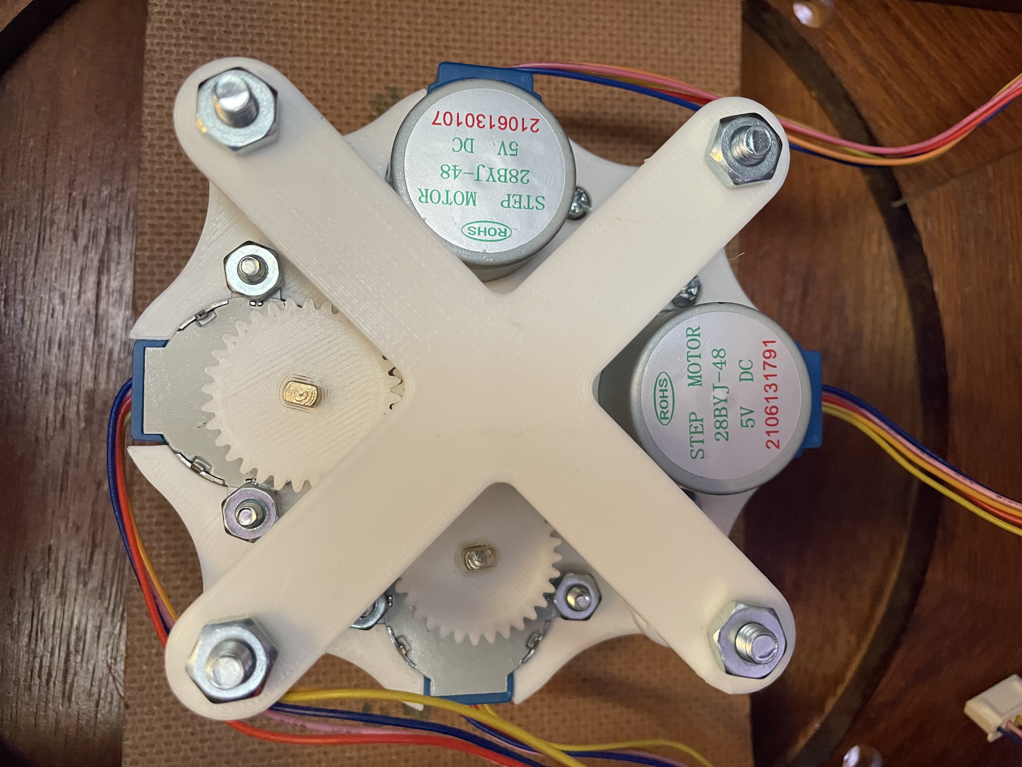
- Wood glue the completed mechanism to the back of the clock face and clamp to let dry.
Assembly
- Before re-attaching the clock face, find locations inside the clock body for all of your motor controllers and ESP32. I did not print a mount for my ESP, it’s just hanging out back there.
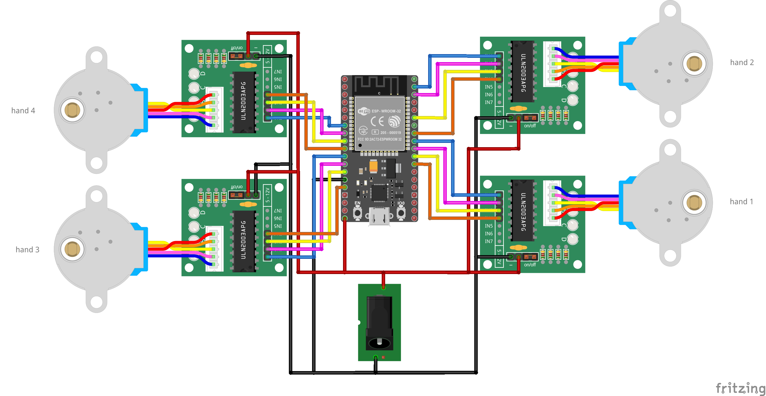
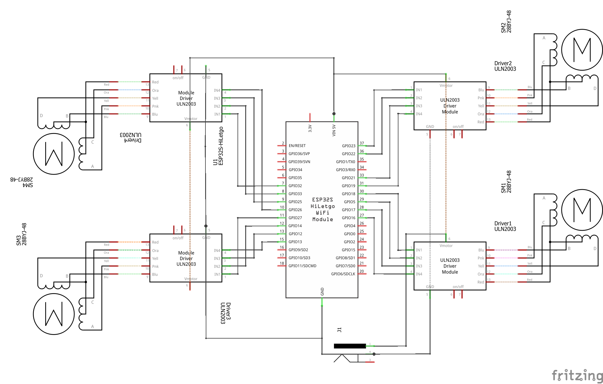
- Wire up everything inside (except the motors, which are on the clock face). The wiring diagrams are below. The only soldering you will need is to make the power harness. The ESP32 board and each of the ULN2003 boards need 5V power.
- Re-insert the glass
- Attach the clock face, watch out for wires, and triple check nothing got unseated during handling.
- Plug in the motors. Which board you plug each motor into matters if you want to use the out of the box firmware for your ESP32! Check the diagram!
- Wire management
- Attach the hands to the face of the clock and align them all to the same location, probably “Home”.
- Power it on and try moving each motor in the Home Assistant Developer Tools “Services” section.
- Troubleshoot and try again :)
Wiring Diagrams
Breadboard
Schematic
Home Assistant
Zones
Home Assistant Zones are the star of the show here. Set up as many Zones as you can for the locations on your clock face. Don’t worry now if the Zone shares the same name as the location on the clock. Not everyone in the household will work at the same place or go to the same school for instance. Name them what they are, we will account for that in the template sensor we create later.
Template Sensors
To map Zones to locations on the clock and implement some additional logic for locations like “Traveling”, “Lost”, and “Vacation” we will be using a Template Sensor in Home Assistant. You can see what mine looks like below:
sensor:
  - platform: template
    sensors:
      jason_presence:
        value_template: >
          {% if is_state('person.jason', 'home') %}
            Home
          {% elif is_state('person.jason', 'not_home') or is_state('person.jason', 'Library') %}
            {% if distance('device_tracker.jasons_iphone') > 80 %}
              Vacation
            {% elif as_timestamp(now()) - as_timestamp(states.person.jason.last_changed) > 86400 %}
              Lost
            {% elif is_state('sensor.jasons_iphone_activity', 'Automotive') %}
              Traveling
            {% else %}
              Away
            {% endif %}
          {% elif is_state('person.jason', 'Nana') or is_state('person.jason', 'Gran') %}
            Parents
          {% elif is_state('person.jason', 'Son School') or is_state('person.jason', 'Daughter School') %}
            School
          {% elif is_state('person.jason', 'Dentist') %}
            Doctor
          {% elif is_state('person.jason', 'Charlotte FC') %}
            Event
          {% else %}
            {{ states('person.jason') }}
          {% endif %}
To better understand the logic here, I have a Zone for “Library”. That is where my Wife works, but I do not. I want the “Away” logic to run when I am there. For my “Away” logic, there are 4 possible “Away” states:
- Vacation: Away, but > 80 km from home.
- Lost: Away for more than 24 hours excluding “Vacation”.
- Traveling: Away but iPhone reports activity as “Automotive”, excluding “Vacation” and “Lost”.
- Away: Simply not home when none of the above special states are met.
Children
The children aren’t old enough for phones yet, and cheap GPS devices targeted for Kids are notoriously insecure. Because of this, I am simply using an Input Select with all of the clock face locations for the kids hands currently. You can then create automations to automatically change them under certian conditions. For example, if my wife or I enter the Zone for a child’s school in the morning, we can place them at “School”. Same thing with picking them up in the afternoon. When they get old enough, this can all be automated through the Mobile App like it is for the adults.
Blueprint
The blueprint is meant to create an automation to control each hand. There is a detailed description in the blueprint on how it should be configured. Click the link below to import it!